Creating a TVC System
Introduction
One of the most ambitious parts of my rocket project was building a custom thrust vector control (TVC) system. Instead of relying only on aerodynamic stability, the goal was to actively control the rocket’s direction during flight using a movable motor mount controlled by servos.
This project combined:
- Mechanical design
- Electronics integration
- 3D printing
- Embedded systems
- Stabilization coding
The TVC system works alongside the flight computer to constantly adjust the rocket’s thrust angle during flight in order to maintain stability.
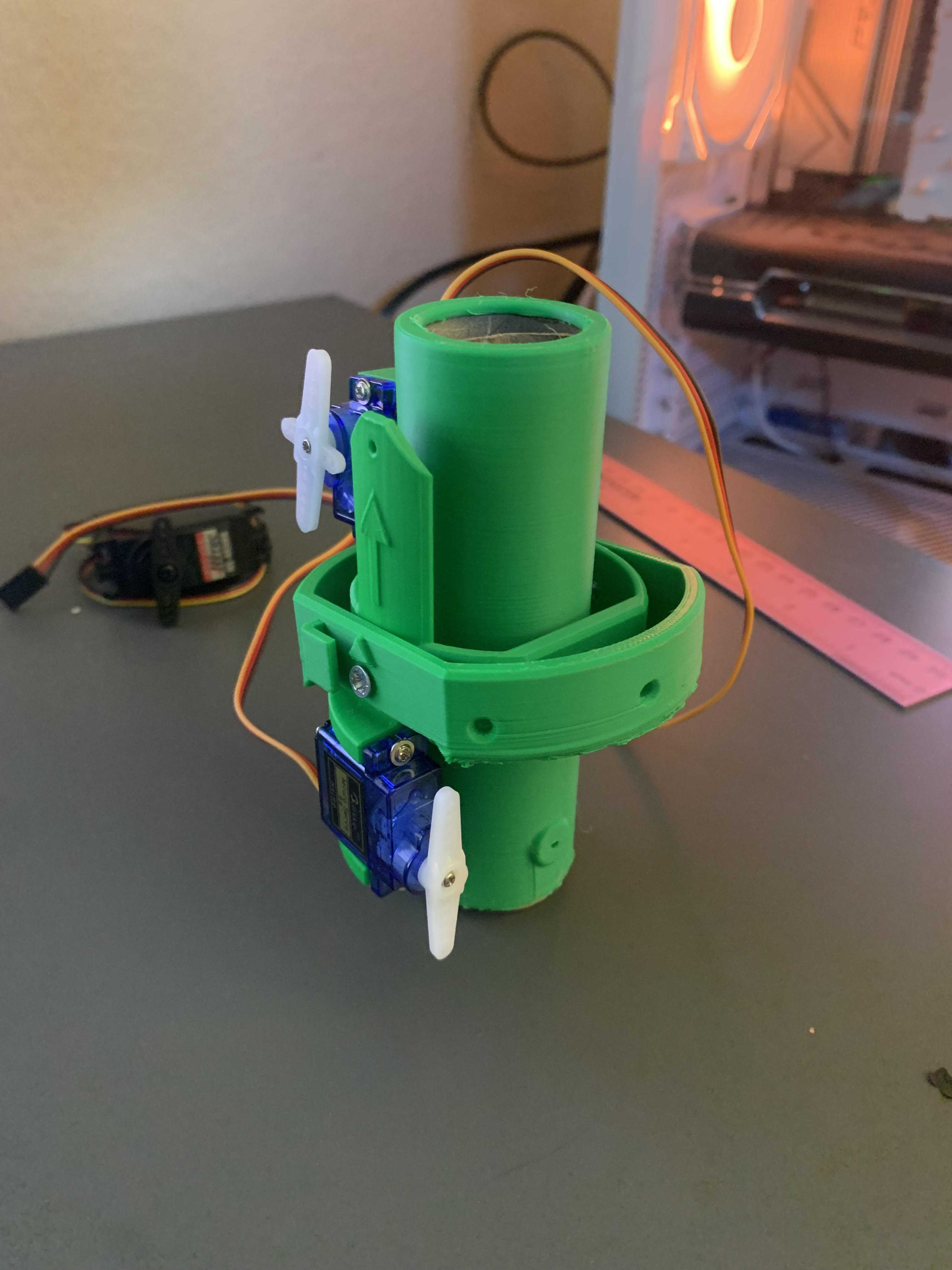
The Gimbal Design
The core of the TVC system is the gimbal mechanism, which allows the motor mount to pivot in multiple directions.
For the gimbal CAD, I used a design originally created by Canine Defense Technologies and modified parts of the setup to better fit my rocket and electronics layout.
The design needed to:
- Move smoothly with minimal friction
- Stay lightweight
- Handle servo movement precisely
- Fit securely inside the rocket body
One of the biggest lessons I learned during assembly was how important tolerances are in moving systems. Some early versions were too tight, which created friction and made the servos struggle to move the mount properly.
Even small resistance in the gimbal caused:
- Servo jittering
- Slower corrections
- Higher power draw
- Less precise movement
I ended up reworking and adjusting parts of the system multiple times to improve movement and reduce mechanical resistance.
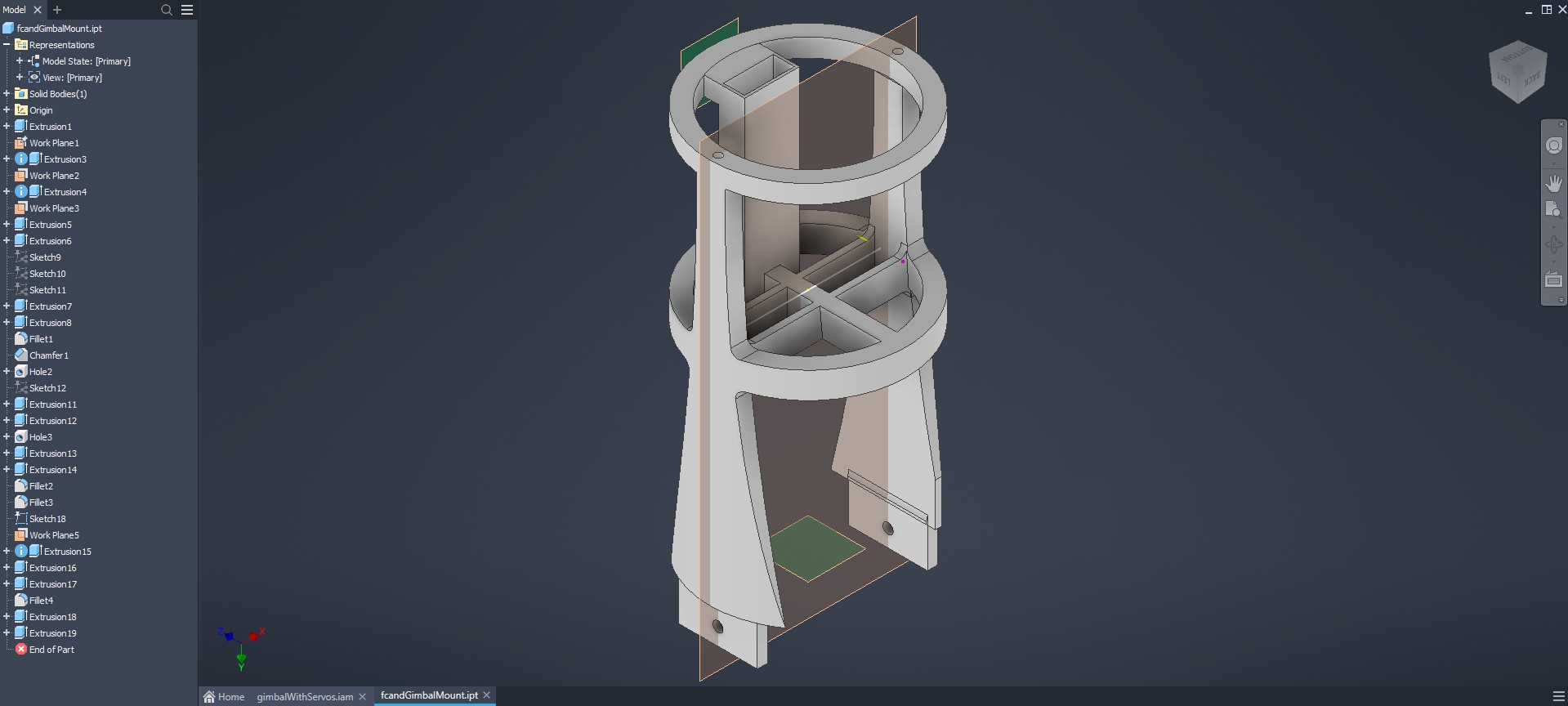
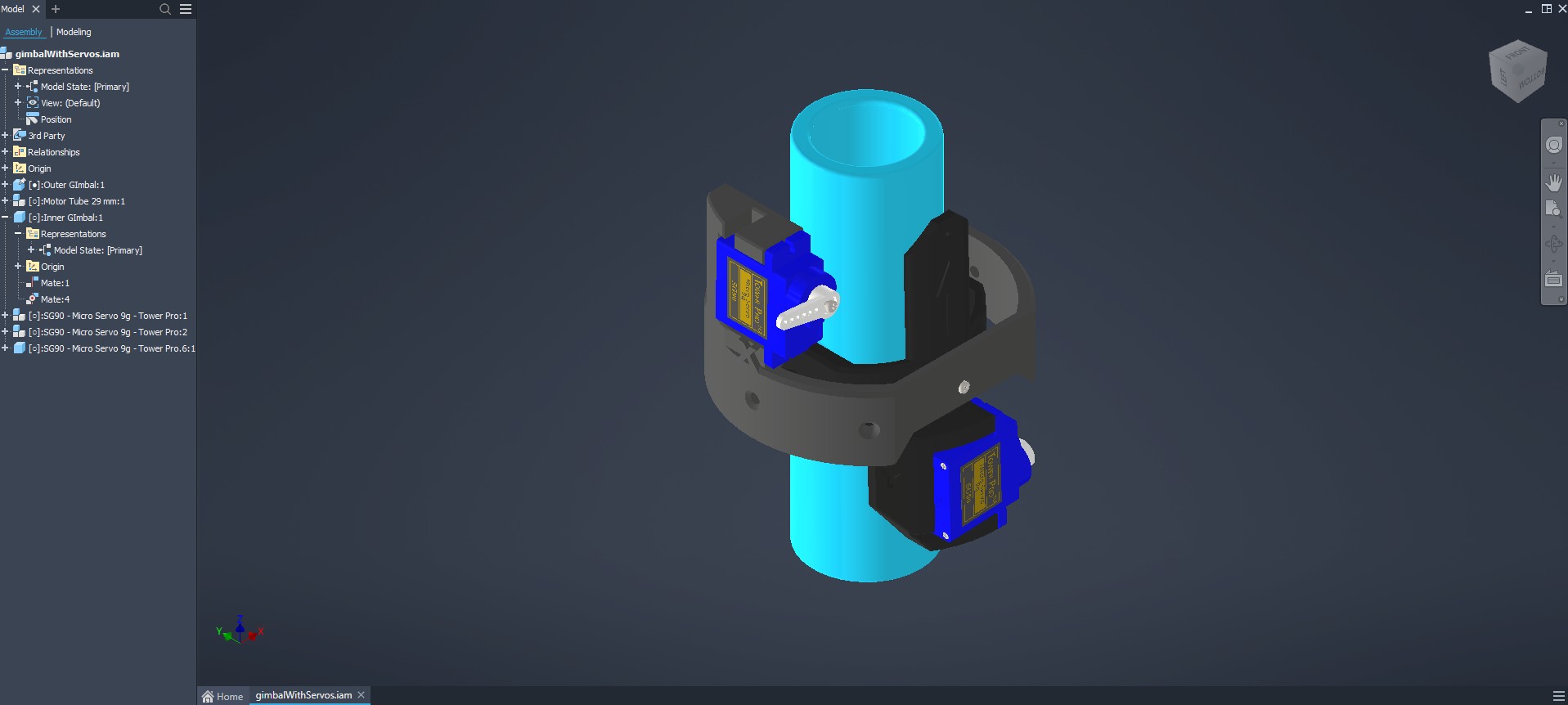 Gimbal CAD based on a design from Canine Defense Technologies
Servo Selection
To actuate the gimbal, I used 9g micro servos because they were lightweight, compact, and powerful enough for the scale of the system.
The servos connect directly to the flight computer and receive stabilization commands in real time.
Some challenges with the servos included:
- Vibration during rapid movement
- Tuning movement speed
- Preventing mechanical binding
- Keeping the linkage geometry aligned correctly
Even though the servos are small, they play a massive role in the overall stability of the rocket.
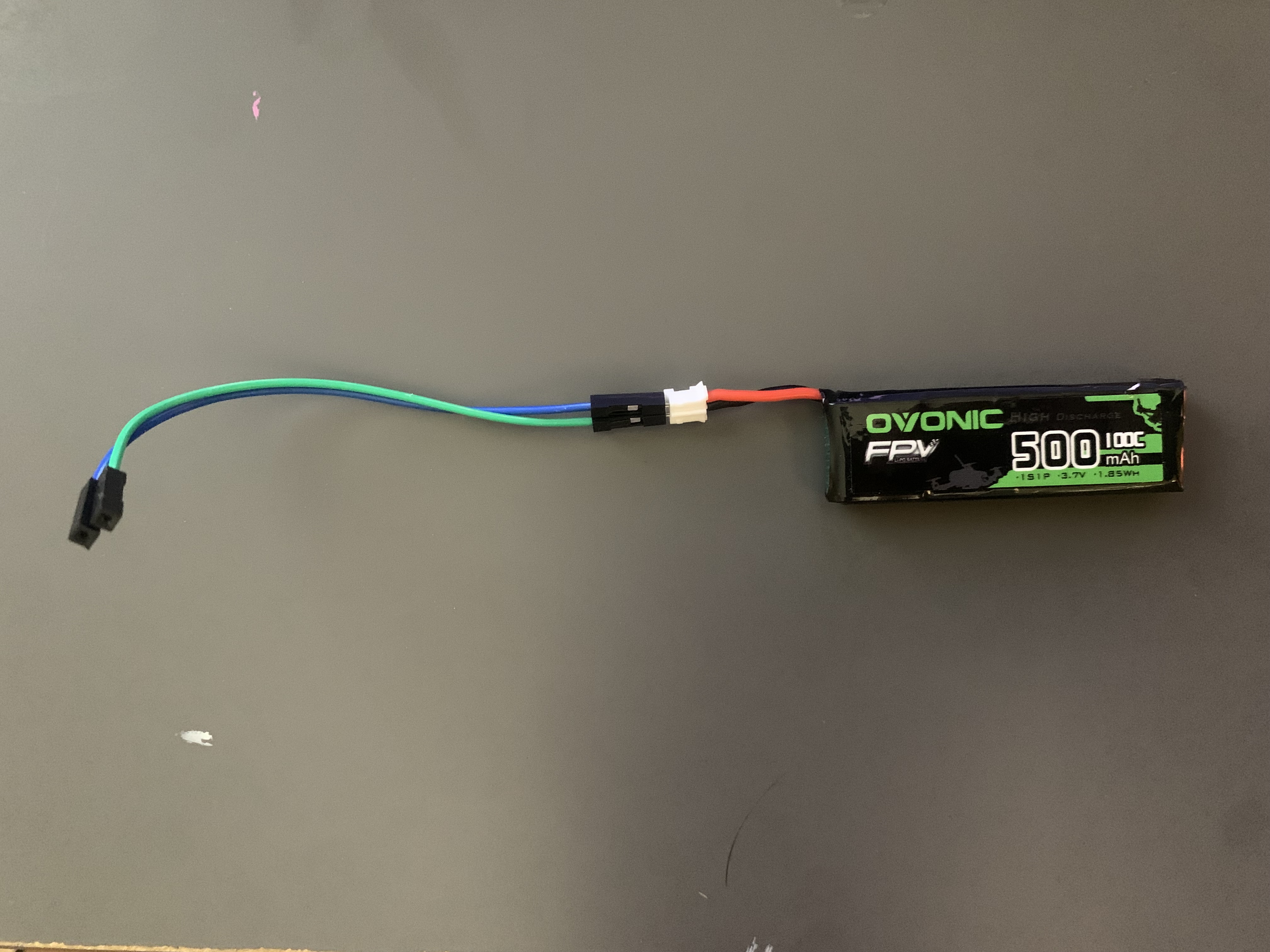
Power System
For power delivery, I used a 500mAh 100C FPV battery to provide enough current for both the flight computer and the servos.
Power management became more important than I originally expected because servo movement can create sudden current spikes. A weak or unstable power system could cause:
- Brownouts
- FC resets
- Unstable servo behavior
- Sensor issues
The FPV battery provided a compact but powerful solution that could handle the demands of the system while still fitting inside the rocket.
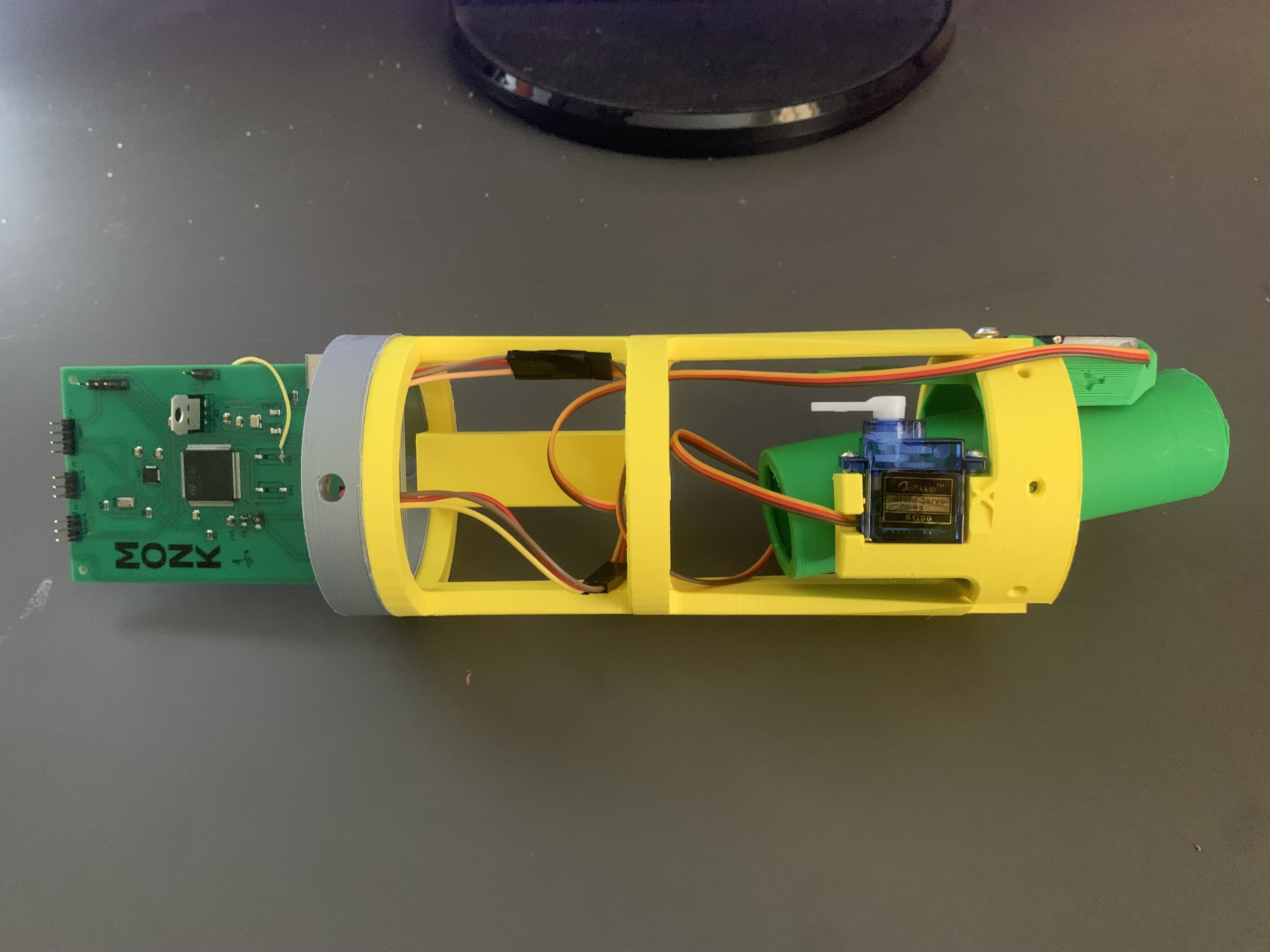
Flight Computer Mount
One challenge was figuring out how to securely mount the flight computer while still keeping the wiring manageable and accessible.
I designed and printed a dedicated FC mount that:
- Secured the electronics during flight
- Protected wiring connections
- Reduced movement from vibration
- Allowed easier maintenance and debugging
The mounting system also helped organize the internal layout of the rocket so components could be removed and tested individually.
Wiring & Integration Mount
As the project grew more complex, wiring management became increasingly important.
I created a separate mount to:
- Connect the TVC assembly and flight computer together
- Route servo wires cleanly
- Prevent cables from interfering with moving components
- Keep the internal structure organized
Without proper wire management, the system quickly became difficult to troubleshoot and maintain.
This mount ended up becoming one of the most important structural parts of the entire assembly because it tied all the major systems together.
Assembly Challenges
Putting the entire TVC system together revealed a lot of issues that didn’t appear in CAD.
Some of the biggest problems included:
- Gimbal tolerances being too tight
- Servos struggling against friction
- Wires interfering with movement
- Alignment issues between components
- Constant iteration and reprinting
This project taught me that even when a design looks perfect digitally, real-world assembly always introduces new challenges.
Most of the progress came through testing, redesigning, and improving small details over multiple iterations.
What I Learned
Building this TVC system gave me hands-on experience with:
- Aerospace control systems
- Mechanical design
- Embedded electronics
- CAD iteration
- Power systems
- Rapid prototyping
More importantly, it taught me how interconnected engineering systems really are. A small issue in one area — like friction in the gimbal — can affect software tuning, power usage, and overall system performance.
Even though the system is still evolving, this project has been one of the most challenging and rewarding engineering experiences I’ve worked on so far.
Future Improvements
Some upgrades I plan to make in the future include:
- Stronger and faster servos
- Cleaner wire routing
- Improved stabilization algorithms
- Lighter structural parts
- Better vibration isolation
- More precise gimbal tolerances
The project is still improving with every new test and redesign.
Credits
- Gimbal CAD inspiration/design from Canine Defense Technologies
- Custom integration, mounting, wiring, and system assembly designed and modified for this project