First Research Paper
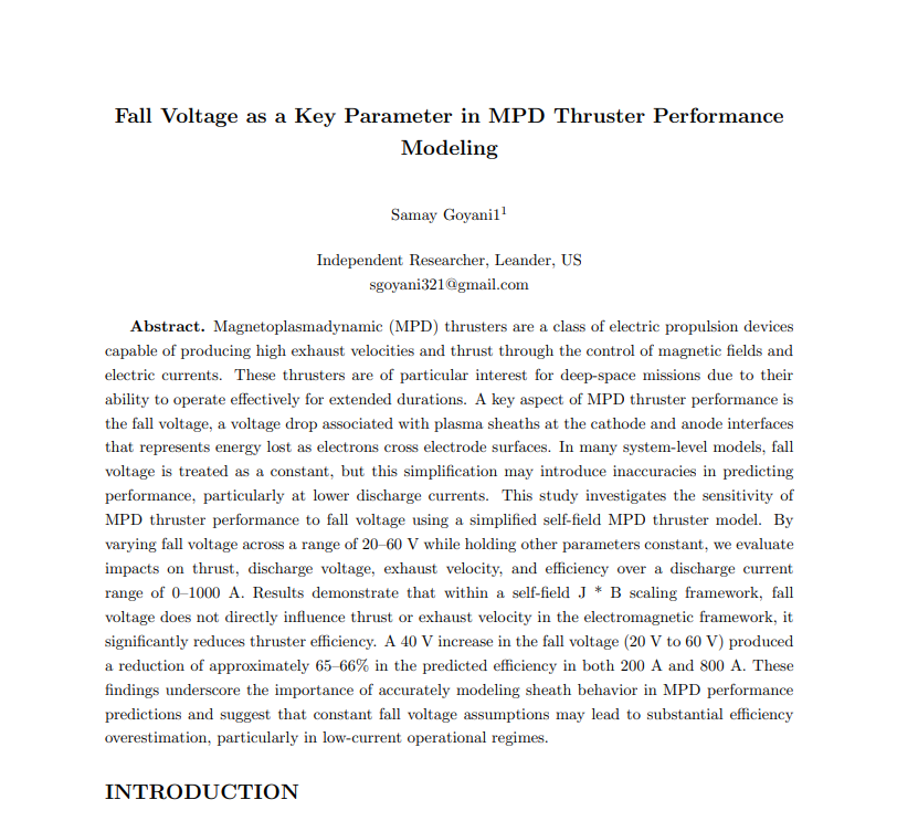
I ended up diving into magnetoplasmadynamic (MPD) thrusters, specifically one small but interesting parameter: fall voltage.
This post is basically a behind-the-scenes look at how I built the model, graphed it in Desmos, and turned it into a full research-style paper.
The Question That Started It
MPD thrusters generate thrust using electromagnetic forces (J*B). In simplified self-field models, thrust scales roughly with the square of current:
T = a I ^2
where:
I = discharge current
a = proportionality constant
This part was pretty simple, but when I started looking into efficiency, I noticed something interesting.
Fall voltage is essentially a voltage drop in the plasma discharge that doesn’t directly contribute to accelerating propellant. It’s often treated as a constant in simplified models.
So my question was that if fall voltage doesn’t directly influence thrust, how much does it affect efficiency predictions?
Building the Mathematical Framework
I started with the thrust equation:
T = a I ^2
Then I connected it to mass flow rate and exhaust velocity relationships. Using basic propulsion relations, I expressed exhaust velocity as:
uₑ = T / ṁ
For efficiency, I used:
η = K2 I3 / ṁ(a I + Vfall)
You’ll notice that fall voltage does not appear in the thrust equation, but does in the power input term in the denominator for efficiency.
That means that thrust might stay the same, but efficiency could shift depending on how large that fall voltage term is relative to arc voltage.
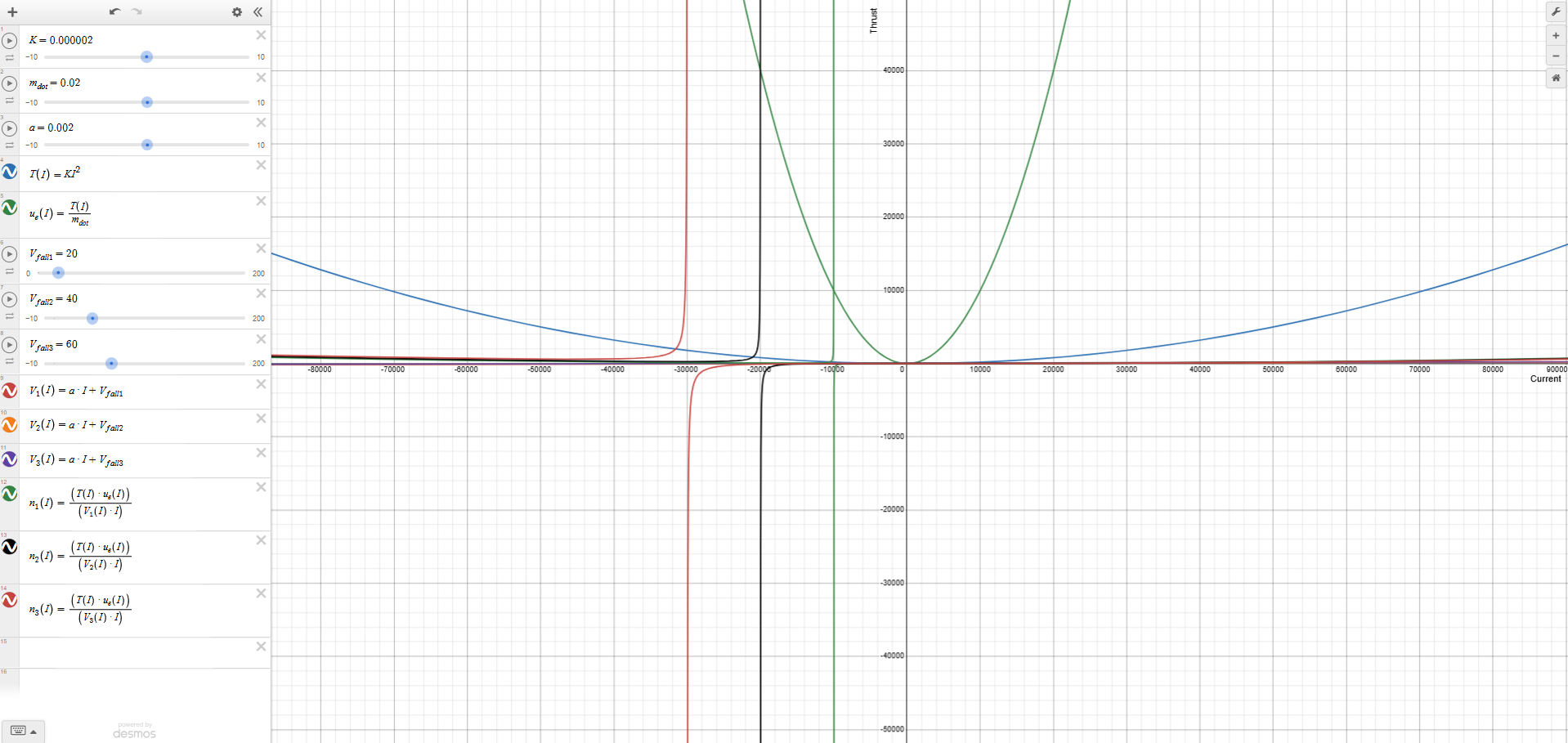
Using Desmos to Visualize It
I went with Desmos instead of MATLAB or Python honestly because it was fast and great for simple parameter sweeps.
What I did:
- Defined thrust as a function of current.
- Defined mass flow rate
- Built the efficiency expression
- Plugged in representative constants.
- Varied current over a reasonable range.
I also testing different constant values of fall voltage to see how sensitive efficiency was.
Here’s an image of the graph with and without constraints.
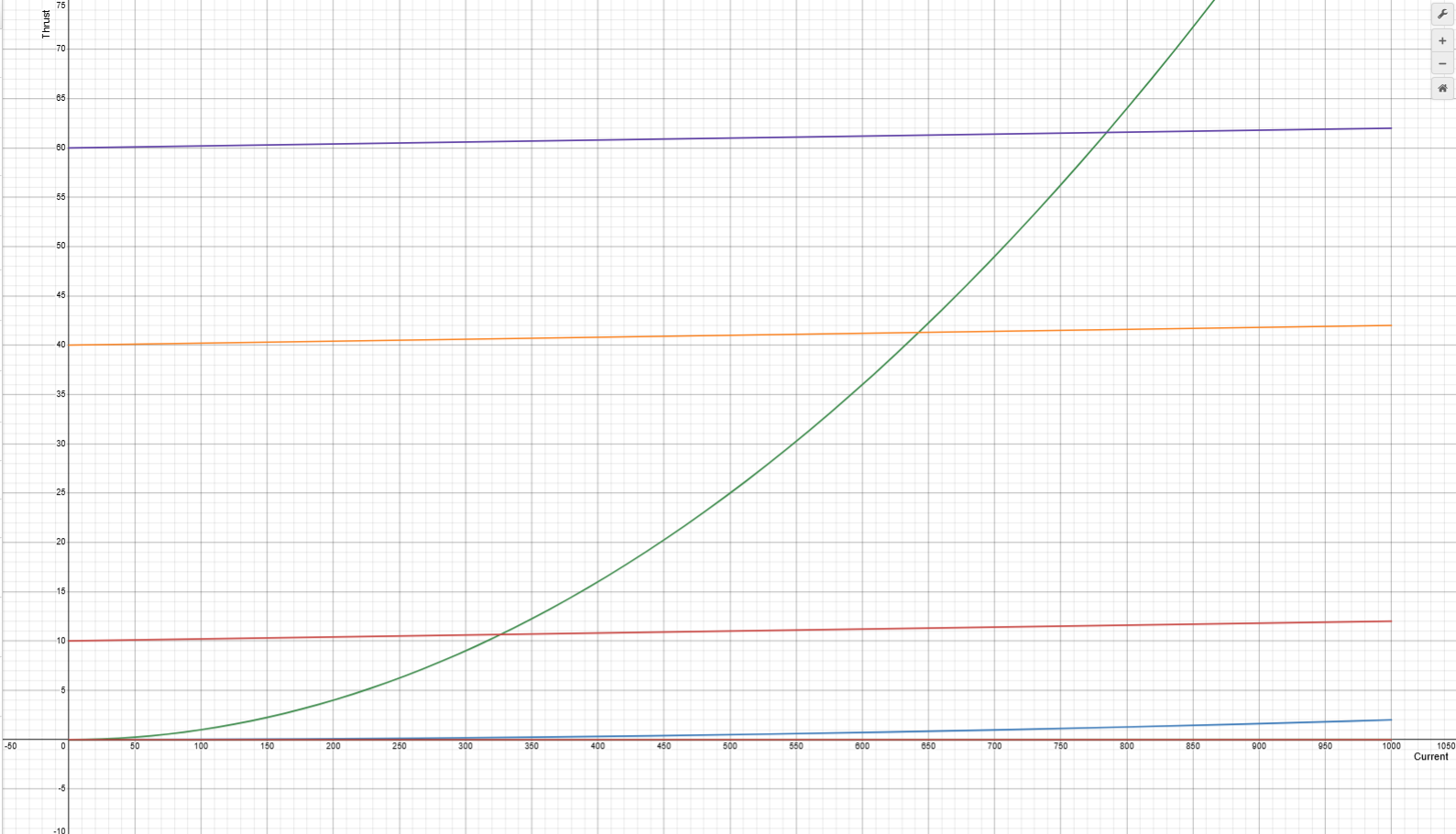
What I saw:
- Thrust curves were completely unaffected by fall voltage.
- Efficiency curves shifted noticeably depending on assumed fall voltage value.
- At higher currents, the relative influence of fall voltage decreased.
- At lower currents, the influence of fall voltage was much higher.
This matched the math, so I wasn’t very surprising, it just made it easier to visualize and experiment with.
Turning It Into a Paper
Once I had the equations and graphs, I organized everything into sections:
- Introduction
- Theoretical Background
- Modeling Framework
- Methodology
- Results
- Conclusions
- References
I also formatting it in a NASA style layout because I wanted to practice writing in a real engineering format.
What I learned
This project definitely wasn’t about creating something new, but it was about learning and understanding modeling assumptions.
Here’s what stood out most to me:
- Small assumptions can significantly influence outcomes
- Analytical modeling forces you to slow down and justify every step.
- Graphing makes patterns much easier to recognize.
This was also my first time writing something that felt like real research.
The Full Paper
You can download the full formatted paper below:
Fall_Voltage_as_a_Key_Parameter_in_MPD_Thruster_Performance_Modeling.pdf